DimmerLink (I2C mode)
By default the DimmerLink comes in UART mode. You need to switch to I2C first!! There are 6 easy steps below on how to do it.
Only 1-channel devices are supported!
Information
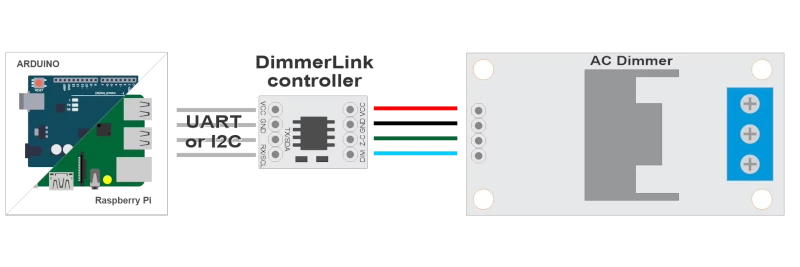
Stop fighting with dimmer libraries. DimmerLink is a tiny plug-and-play controller that handles all the complex TRIAC timing for you. Just send simple commands over UART or I2C — the DimmerLink controller does the rest.
Every maker knows the pain: you integrate an AC dimmer library into your project, and suddenly your lights flicker, your timing breaks, and you spend hours debugging interrupt conflicts. The DimmerLink eliminates this entirely by offloading all timing-critical operations to a dedicated Cortex-M+ micro controller.
Works with
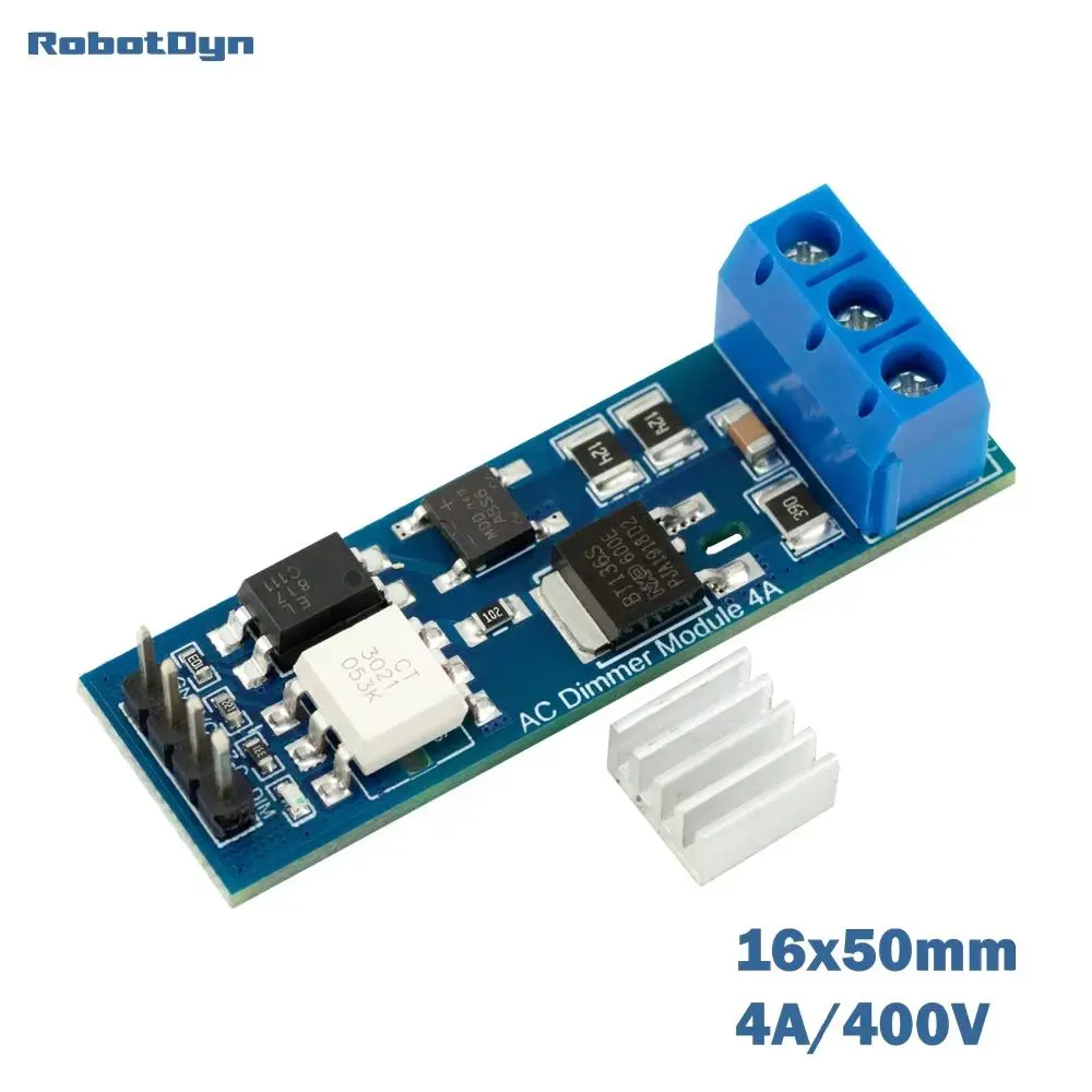
You can also now buy the AC Dimmer with the DimmerLink module directly built in it. Select the DimmerLink(UART/I2C) interface when ordering. This saves you an extra DimmerLink module. Which makes this a pretty cheap, small and simple AC mains dimmer to use.
Make it work with TerrariumPI
In order to make the device to communicate with TerrariumPI a few steps needs to be done.
This is a one time action.
Configure the DimmerLink device to I2C mode.
1 For this you need some extra hardware
- USB-UART adapter (CP2102, CH340, FT232, or similar)
- AC Mains cable with wall plug
2 The USB-UART adapter can be put in the Raspberry PI USB port. With the command dmesg you should see something like below. We are using a FT232R USB UART Dongle.
1
2
3
4
5
6
7
8
9

usb 1-1.3: new full-speed USB device number 4 using xhci_hcd
usb 1-1.3: New USB device found, idVendor=0403, idProduct=6001, bcdDevice= 6.00
usb 1-1.3: New USB device strings: Mfr=1, Product=2, SerialNumber=3
usb 1-1.3: Product: FT232R USB UART
usb 1-1.3: Manufacturer: FTDI
usb 1-1.3: SerialNumber: A50285BI
ftdi_sio 1-1.3:1.0: FTDI USB Serial Device converter detected
usb 1-1.3: Detected FT232R
usb 1-1.3: FTDI USB Serial Device converter now attached to ttyUSB0
3 In oder to make the switch from UART to I2C we need to connect the dimmer to the AC main power. Else the calibration will become ‘stuck’.
Just connect two wires to the connectors N and L (in connectors). Do not plugin the power yet!!!
We are working with live AC main power!!! Be careful with what you do!
4 Now we start the listening for the connection to the dimmer device when we connect it to the USB-UART adapter
screen /dev/ttyUSB0 115200,cs8
The dongle is mostly connected to /dev/ttyUSB0. Look at the last line at step 2 to be sure. It can be that the number is higher than 0 if you have more USB devices connected.
This will open a new screen, were it waits for messages from the hardware device.
Next connect the USB-UART adapter to the device using the following coloring of the adapter wires.
- Green => RX/SCL
- White => TX/SDA
- Black => GND
- Red => VCC
You should now see the following text:
1
2
3

=== TRIAC Dimmer ===
Mode: UART
Calibrating...
And it looks like it is waiting. Now plugin the AC main power, and it should continue.
Now unplug the AC main power, so we can continue safely.
1
2
3
4
5
6
7

=== TRIAC Dimmer ===
Mode: UART
Calibrating...
Phase period: 10200 us [50 Hz]
[DEBUG] curve_type=0 (0=LINEAR,1=RMS,2=LOG)
Temperature protection: DISABLED
UART mode ready
It is very important that the message UART mode ready is shown. Else we cannot give the command to switch to I2C.
At this point, we stop the screen session with the command Ctrl+A, and than press k which is asking to kill the session. Answer with y.
Run the command below to make the dimmer switch from UART to I2C.
echo -en '\x02\x5b' > /dev/ttyUSB0
5 Disconnect the device from the USB-UART adapter and connect to the I2C bus
Run the command sudo i2cdetect -y 1 to see a value of 50. If this is not the case, repeat from step 4.
1
2
3
4
5
6
7
8
9

     0  1  2  3  4  5  6  7  8  9  a  b  c  d  e  f
00:                         -- -- -- -- -- -- -- --
10: -- -- -- -- -- -- -- -- -- -- -- -- -- -- -- --
20: -- -- -- -- -- -- -- -- -- -- -- -- -- -- -- --
30: -- -- -- -- -- -- -- -- -- -- -- -- -- -- -- --
40: -- -- -- -- -- -- -- -- -- -- -- -- -- -- -- --
50: 50 -- -- -- -- -- -- -- -- -- -- -- -- -- -- --
60: -- -- -- -- -- -- -- -- -- -- -- -- -- -- -- --
70: -- -- -- -- -- -- -- --
6 Change I2C address. This is optional, but when you want to use multiple DimmerLink AC dimmers, you can change the address with the command.
Change address to 0x51:
1

i2cset -y 1 0x50 0x30 0x51
Key features
- Zero flickering - hardware-based timing, immune to software delays
- Universal interface - UART (115200 baud) or I2C (address 0x50)
- Wide voltage range - works with 1.8V, 3.3V, and 5V logic levels
- Ultra-compact - only 18×12mm, fits anywhere
- Multiple dimming curves - Linear, RMS, Logarithmic
- Auto frequency detection - works with 50Hz and 60Hz mains
Setup
In order to use the DimmerLink (I2C mode) use the following settings:
Mandatory
- Hardware
- DimmerLink (I2C mode)
- Address
- <I2C Address>,[I2C Bus] where the I2C bus is optional
Ex:0x50
Other settings can be found at the relay setup information